Key features of spool drawings include
Isometric Views
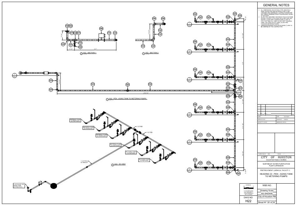
Spool drawings typically present isometric views, which show the three-dimensional representation of the piping components and their connections. This allows fabricators and installers to visualize how the pipes will fit together.
Piping Components
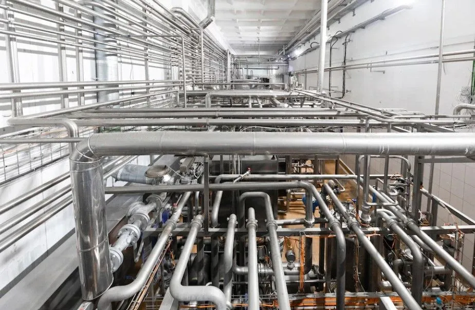
The drawings detail various components of the piping system, such as pipes, elbows, tees, flanges, valves, and supports. Each spool drawing focuses on a specific section of piping, showing the arrangement of these components in that section.
Dimensions and Measurements
Spool drawings include accurate measurements and dimensions for each component, including pipe lengths, diameters, angles, and offsets. This information is crucial for fabricators to cut and assemble the piping accurately.
Material Specifications
The type of material used for each component is specified on the drawing. This ensures that the correct materials are used for each section of piping, taking into account factors such as temperature, pressure, and the substances being transported.
Welding Details
If welding is required to join the piping components, spool drawings may provide details about the type of welds, welding procedures, and welder qualifications. This information ensures that welding is performed according to industry standards.
Supports and Hangers
Spool drawings often include information about the required supports, hangers, and bracing for the piping system. This ensures that the piping is properly supported and secured to prevent sagging or movement.
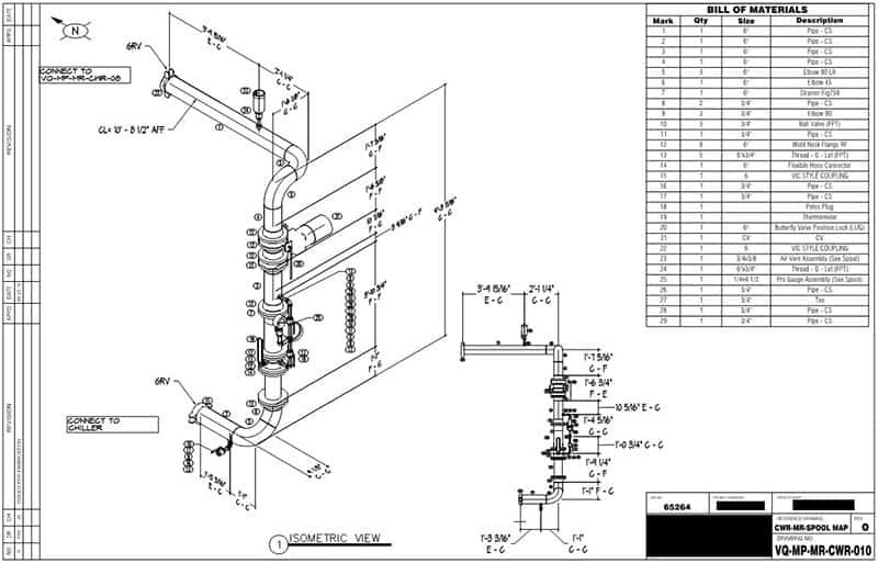
Bill of Materials
A bill of materials (BOM) or material take-off is usually included with spool drawings. This list specifies the quantities and specifications of all the components needed to fabricate and assemble the spool.
Coordinated with Other Trades
Spool drawings are coordinated with other trades, such as structural, electrical, and HVAC systems, to ensure that the piping system fits seamlessly within the overall facility layout.
Fabrication and Installation Instructions
Some spool drawings may include additional instructions or notes for fabricators and installers, such as details about joint preparation, assembly sequence, and specific requirements for each spool.
Revision Information
Like any technical drawing, spool drawings include revision information, dates, and version numbers to track changes and updates made during the design and construction process.
Spool drawings streamline the construction process by providing a clear and detailed roadmap for fabricators and installers. They help ensure that the piping components are fabricated accurately and fit together precisely during installation, reducing the potential for errors and delays.
Spool drawings are detailed representations of individual sections or "spools" of piping or duct-work used in construction projects, particularly in industries such as oil and gas, petrochemicals, power generation, and industrial manufacturing. These drawings provide specific information for fabricators and installers to manufacture, assemble, and install these sections accurately within larger piping or duct-work systems. Spool drawings play a crucial role in coordinating and executing complex projects efficiently.
Key components of spool drawings include
Geometry and Dimensions
Spool drawings include accurate measurements, dimensions, and angles for each piping or duct-work component within the spool. This information ensures precise fabrication and installation.
Detailed Components
The drawings illustrate all the components needed for the spool, including pipes, elbows, bends, reducers, tees, valves, flanges, gaskets, and other fittings.
Material Specifications
Spool drawings specify the type of materials to be used for each component, taking into consideration factors like temperature, pressure, and the substances being transported.
Welding Details
If welding is required, the drawings provide welding specifications, joint preparations, and welding symbols to guide fabricators and welders.
Connection Points
Spool drawings indicate where each component connects to adjacent sections, ensuring proper alignment and fit.
Supports and Hangers
Information about required supports, hangers, brackets, and other structural elements necessary to hold the spool securely in place may be included.
Bill of Materials
A detailed list of all the materials needed to construct the spool is often provided, helping with procurement and inventory management.
Coordinated with Other Trades
Spool drawings are coordinated with drawings from other trades, ensuring that the spools fit seamlessly into the overall building or facility design.
Installation Guidelines
Some spool drawings may include instructions for the installation sequence, alignment procedures, and other guidance for on-site assembly.
Revision Control
Like all technical drawings, spool drawings are often subject to revisions and updates, and they include revision information to track changes.
Spool drawings are typically created using Computer-Aided Design (CAD) software, which allows for precise visualization and measurement of the components. These drawings facilitate efficient communication between design teams, fabricators, and installers, ultimately contributing to the successful completion of complex construction projects.
Spool Drawings from BIM
Spool drawings derived from Building Information Modeling (BIM) processes offer an enhanced level of coordination, accuracy, and efficiency in the design, fabrication, and installation of piping or duct-work systems. BIM is a digital representation of a building's physical and functional characteristics, and it provides a collaborative platform for architects, engineers, contractors, and other stakeholders to work together on a construction project. When creating spool drawings from BIM models, several advantages can be realized.
Accurate Representation
BIM models provide a detailed and accurate representation of the entire building or facility, allowing for better visualization and understanding of how piping or duct-work systems fit into the larger context.
Integrated Design
BIM enables seamless integration of various building systems, such as structural, architectural, electrical, and mechanical components, ensuring that the spool drawings are coordinated with other disciplines.
Parametric Modeling
BIM software often uses parametric modeling, allowing changes made to the model to automatically update in related drawings and documentation, reducing errors and inconsistencies.
Data-Rich Information
BIM models can contain a wealth of data beyond just geometry, including material specifications, fabrication details, cost information, maintenance schedules, and more.
Automated Generation
Spool drawings can be generated directly from the BIM model, automating the creation process and reducing manual drafting efforts.
Clash Detection
BIM software can identify clashes or conflicts between different building systems early in the design phase, helping to prevent issues during fabrication and installation.
Efficient Changes and Revisions
When design changes occur, the BIM model can be easily updated, and the corresponding spool drawings can be quickly regenerated, maintaining consistency throughout the project.
Visualization
BIM models can provide visual walkthroughs and simulations, allowing stakeholders to understand the spatial relationships of the piping or duct-work within the larger building context.
Documentation Management
BIM facilitates better documentation management, making it easier to track revisions, access historical data, and ensure that the most current information is being used.
Collaboration
BIM fosters collaborative communication among project team members, enabling real-time sharing of information and reducing miscommunication.
In summary, spool drawings derived from BIM models offer a modern and streamlined approach to the design and construction of piping or duct-work systems. They enhance coordination, accuracy, and efficiency while promoting collaboration and reducing the potential for errors during fabrication and installation.